Special Aircraft Service

Please login or register.

Login with username, password and session length
Advanced search  
Pages: [1] 2   Go Down

Author Topic: Steampunk is not dead: sniperton's project  (Read 3240 times)

0 Members and 1 Guest are viewing this topic.

sniperton

  • member
  • Offline Offline
  • Posts: 1226
Steampunk is not dead: sniperton's project
« on: August 17, 2019, 01:22:55 PM »

DIY is fun. Whatever it costs you in time and money, it's definitely fun.

Your wife is happy because you duly tidy up the hall after each DIY session (what you wouldn't do otherwise), and you're happy because you can buy new tools and experiment with materials never used before.

A few years ago I made a DIY rudder that I'm still using today. It's a robust metal construction with a Hall sensor and the cannibalized electronics of my former Logitech joystick. Now the electronics is gone, I need a new controller.

It was Mike's project that gave me the idea to incorporate my rudder into a new project which should be a HOTAS, a button box and a throttle combined in one. Here is the 3D model:


The idea is that I need
(1) a throttle with 12 buttons (modifiers, FOV change, map control, comms, wheel brake, etc.)
(2) a box with the rest of the frequently used buttons (see below)
(3) and an electronics hosting all these and my rudder.


The plan is to use rotary encoders for trims, potmeters for mixture/RPM/turbo, Hall sensors for throttle and rudder, and push buttons and rocker switches for the rest.

I'll describe my project in the order of (1) throttle, (2) box, (3) electronics.
Expect 2 to 3 weeks for getting from 1 to 2, from 2 to 3.
Logged

sniperton

  • member
  • Offline Offline
  • Posts: 1226
Part I: the handle
« Reply #1 on: August 17, 2019, 01:24:21 PM »

The throttle handle or grip.

First I designed the whole thing in FreeCAD to see if there's room for everything, but afterwards I also made a 1:1 cardboard modell to check ergonomics and to adjust my design accordingly.


To the left the cardboard modell, to the right the unfolded, cut-out version from 1mm aluminium plate (see the shopping list below). Buttons are temporarily inserted to check hole sizes.


The unfolded plate is already cut into two, and is being bent on a 50mm diameter tube. Note my "workshop" in the hall of our flat.


3D-check of the resulting pieces. Note that they are directly fastened with screws onto two 20x2mm aluminium bars, which are bent to 90 and 45 degrees, respectively. The nylon rods substitute the closure piece still missing.


To the left, the two pieces already covered with carbon vinyl wrap. To the right, the cardboard modell for the closure piece and its bent aluminium counterpart already wrapped in vinyl.


The handle partially assembled and the buttons already inserted. Note the wires connecting the box to the handle, running between the two bars and ending in mini-fit connectors.


Wiring done, here checking connections with a multimeter.


The whole thing assembled. Front view, thumb side.


This gives you an idea of the size. I have relatively small hands (glove size 8 ), and I can comfortably reach each button either with my thumb tip, or thumb base (or whatever the correct English for that).


For comparison, the rear side. The two big red buttons are the modifiers, the rocker switch fits into the gap between ring finger and middle finger.


Shopping list:
- aluminium bar, 2x20mm, 50cm (OBI/Praktiker)
- aluminium plate, 1mm, 20x30cm (hobby shops)
- screws (I mostly used M3 hex screws, from 6mm to 12 mm)
- 8pin mini-fit connectors, 4 plugs, 2 sockets
- corresponding number of crimps
- 8-core cable, 1m
- 10 buttons (I used 3 different types of momentary push buttons and 1 rocker switch)
- vinyl wrap (it's cosmetic, 40x50cm would suffice, but you can't get such a small piece)
Logged

sniperton

  • member
  • Offline Offline
  • Posts: 1226
Part II: the box
« Reply #2 on: August 17, 2019, 01:25:01 PM »

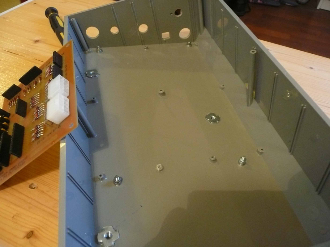
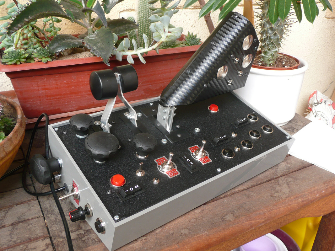
Here provisions have been made for additional controls and connectors on the side. The special nuts you see on the bottom have been heat-sunk and serve to fix the case from below.


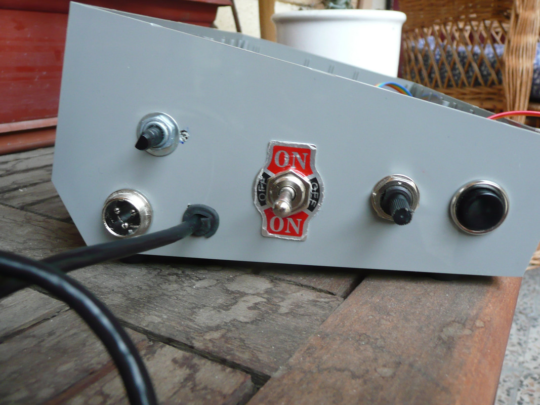
To the lower left is a microphon connector for the Hall sensor in the DIY rudder, above it an encoder (for pitch trim), to the right a 2-way momentary switch (for whatever), a pot (for whatever), and a push button.


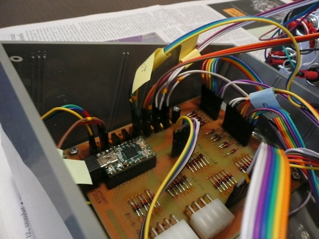
The PCB already inserted, the wiring done, waiting for the rest of the wires to come...


Now let's turn to the cover. Once again I made a 1:1 print-out from FreeCAD...


... and produced this cover-piece. As dampers for the levers I applied cheap black PVC from OBI (10 x 10 mm and 10 x 20 mm L-profile)


Buttons and switches already inserted:


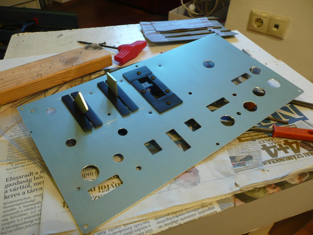
To the lower left two encoders, then two pots with levers, than the mechanics of the throttle grip. The pots:


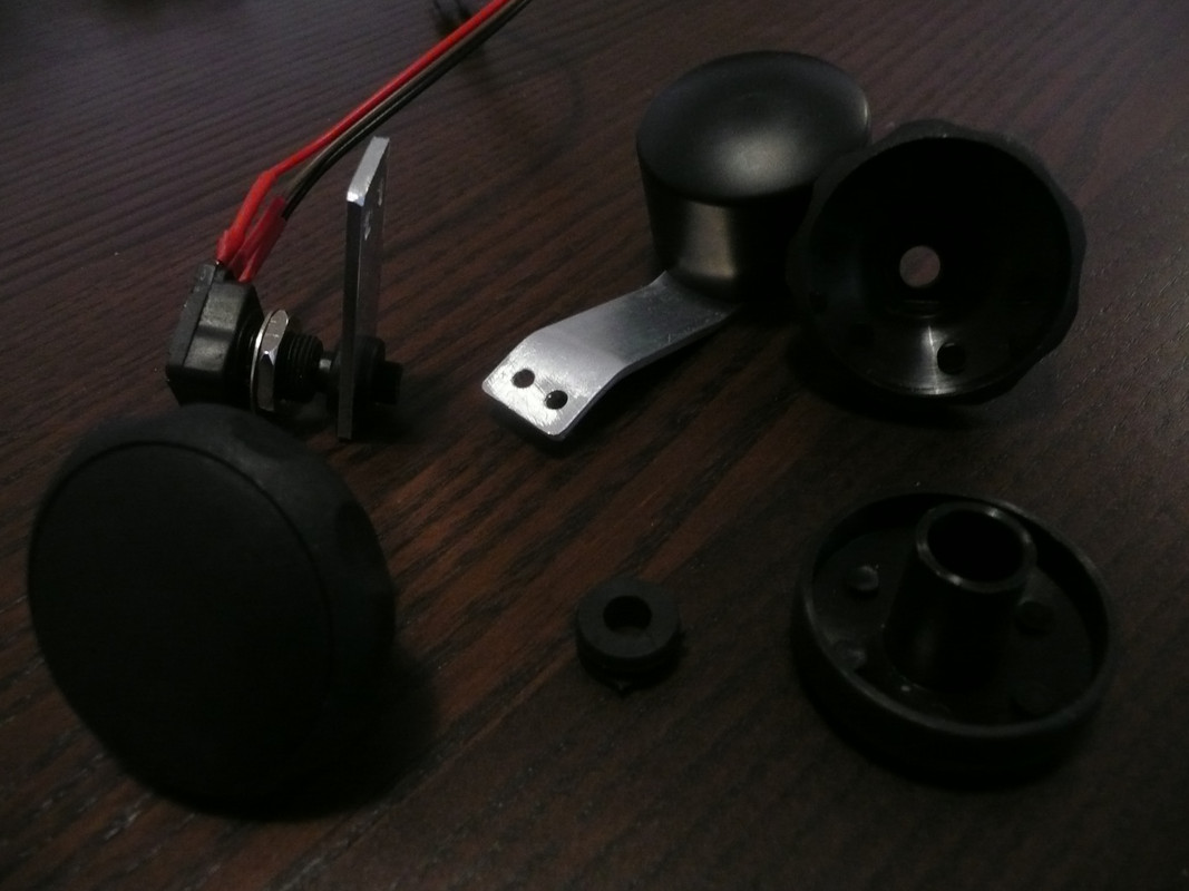
The basic trick is that most pots have a 6 mm diameter shaft, and you can buy rubber grommets with an inner diameter of 6 mm. Take the grommet, pull it onto the shaft, and you'll be able to operate the pot with a lever. If it's tight enough there's no friction.

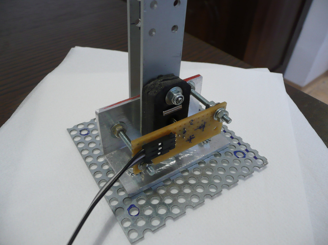
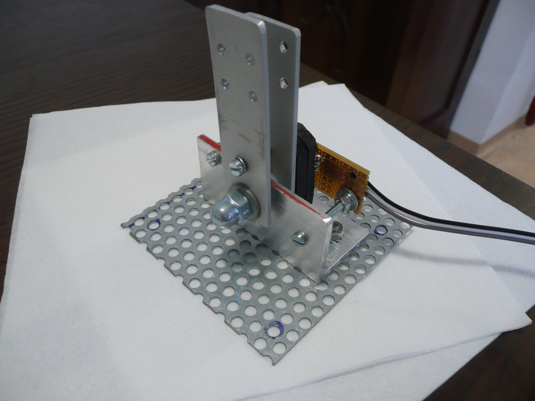
Here is the throttle mechanics with a Hall sensor. Instead of bearings and dampening, I used nylon washers between levers and the base plate. Resistance can be adjusted by a screw. We'll see how it works out.


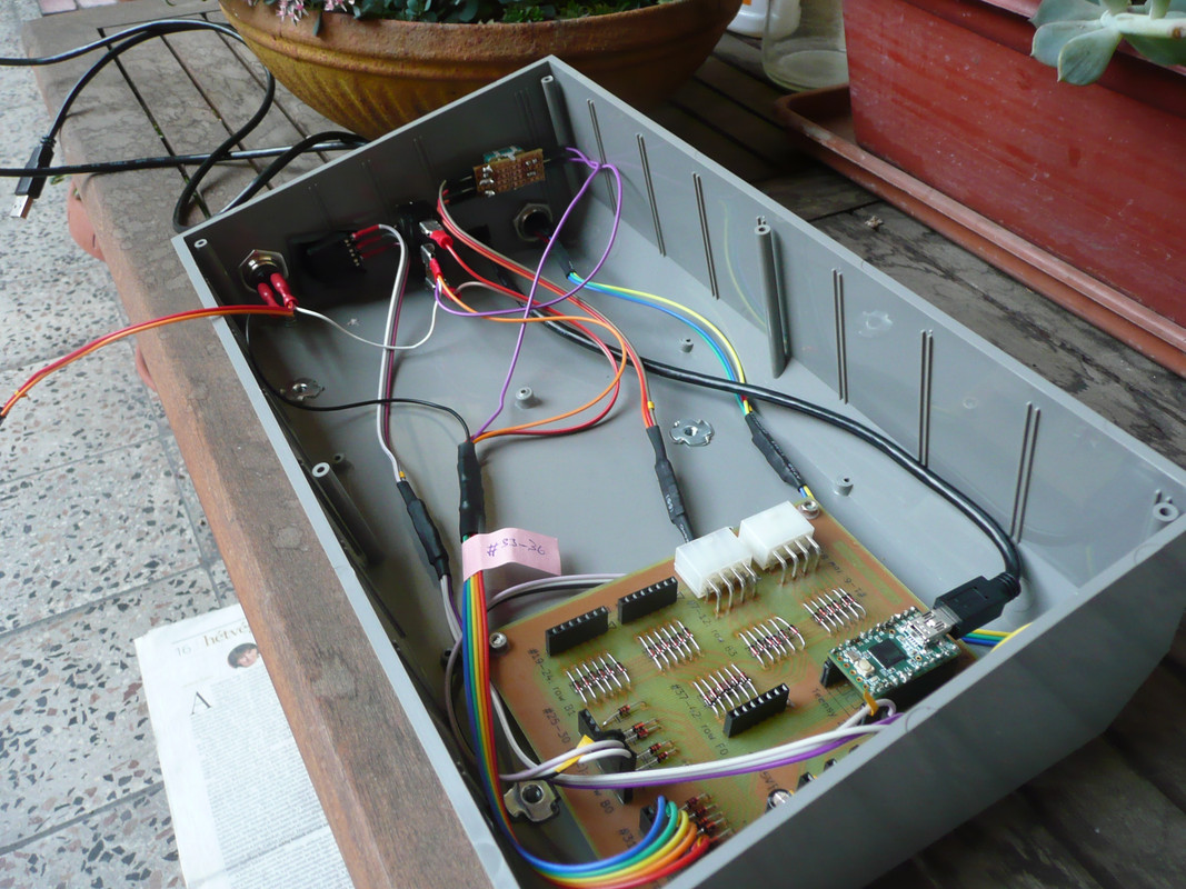
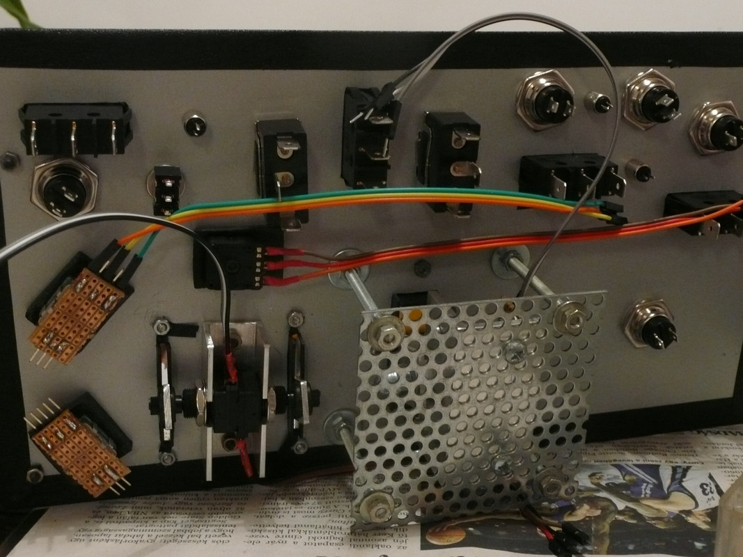
All the wiring done and is ready to be connected to the PCB:


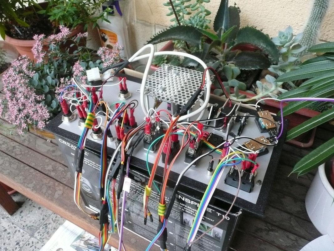
A bit more order in the box. Connecting wires to the PCB:


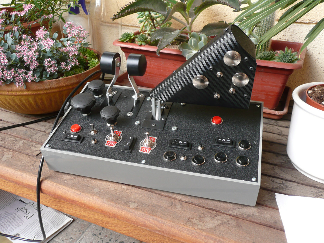
Now you can imagine my facepalm when I realized that I made a button box with 6 more buttons than my PCB is designed for. It's a sad and true fact, but luckily my wife decided not to divorce. This is the end product, still under testing and lacking the knobs etc.

The box fully assembled.


Tonight I made my first full tests and the Teensy flew!!! One of the pots proved to be defective and shall be replaced, and of course the button group to the extreme right is not operational due to my inability to count properly... And some fine-tuning is still needed for the encoders.

Shopping list:
- TEKO 364.8 box (310 x 170 x 90 mm, sloped, https://www.tme.eu/hu/en/details/364.8/desktop-enclosures/teko/)
- vinyl wrap for the cover plate
- USB cable A to mini-B, 1.8 m
- Allegro 1302KUA-T linear Hall sensor for the throttle (there's another one in the rudder)
- 4 pcs neodymium magnets, 10 x 5 x 1 mm each
- 4 linear pots, 10 kOhm
- 3 rotary encoders (these are fine: https://www.tme.eu/hu/en/details/pec16-4220f-s0024/incremental-type-encoders/bourns/)
- 12 large push buttons (including those on the throttle grip)
- 8 small push buttons (including those on the throttle grip; these are fine: https://www.soselectronic.com/products/miyama/ms-402-schwarz-19001)
- 5 pcs (ON)-OFF-(ON) switches with lever (those belonging to this family are fine, the rest are either crap or hard to operate: https://www.soselectronic.com/products/no-name/kn3b-103a-61641)
- 4 pcs (ON)-OFF-(ON) rocker switches (very hard in feel compared to push buttons)
- various types of connectors and pin-headed jumper wires
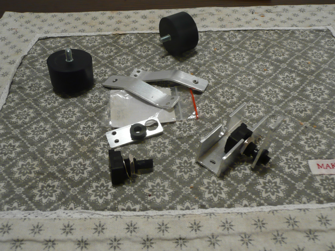
- for the throttle mechanics: perforated iron plate, 30 x 30 x 3 mm aluminium L-profile, 20 x 2 aluminium bar, M6 and M3 screws
- for the pots with lever: 20 x 20 x 2 mm aluminium U-profile, 15 x 2 mm aluminium bar, cabinet knobs from IKEA
- as large pot knobs are bloody expensive, I used M6 nut handles instead from a local hardware shop. These are made of 2 plastic parts for an ordinary M6 nut to be inserted, but if you replace the nut with a rubber grommet, it becomes a perfect and very cheap large knob for pots and encoders.


See below my other experiences, remarks, and suggestions.
Logged

sniperton

  • member
  • Offline Offline
  • Posts: 1226
Part III: the electronics
« Reply #3 on: August 17, 2019, 01:25:37 PM »

My project has been hampered for long by the Teensy++ 2.0 card not arriving from Hong Kong. After two months of waiting I lost my patience and came to the conclusion that it has been lost. I looked around in local electric shops to find out what I could have instead, and following Mike's advice (which was essential as always) I grabbed a Teensy 2.0 for double the price I would have paid for the Hong Kong version that I never got in my hands.

This necessitated the re-designing the PCB of course, but finally I could test the real thing on a breadboard. The tests were limited to certain functions, but they went fine, so I decided to produce the board. My wife made the prints, I ironed them onto the panel, sodium persulfate did the rest, and I drilled 200 holes and soldered 200 pins into place just to find out that I made a very silly mistake when designing the circuit schematics. Anyway, here's my 1st board that proved to be useless (apart from using it for further testing).


I paid the price for not having made any PCB in the past 30 years, but I re-learnt soldering and gained a lot of experience which is priceless. As I do everything by hand, pads have to be much bigger than by default, and generally everything has to have higher tolerance values than what your design software suggests.

Here is my schematics. It's a button box for 8 analog inputs (3 Hall sensors and 5 pots) and 7x6 buttons (including 3 rotary encoders)


And here is my PCB design:


To the right the print-out from KiCad, to the left what it looks like after washing off the paper after ironing this image onto a panel:


Magic in progress. Sodium persulfate doing its job while eating up the copper. The process is very slow, takes more than one hour, but wife could be assured you wouldn't poison the whole family in an instant.


After the chemical process completed, using an abrasive for 5 to 10 minutes produces the end result.


200 holes drilled, 200 solderings done. This 2nd version looks a bit better:


Front side:


Shopping list:
 - Teensy 2.0 (the most expensive item)
 - one-sided panel 0.8 x 120 x 100 mm
 - mini-fit sockets (2 x 8p)
 - various pin sockets (8 x p3, 4 x p7, 1 x p9, 2 x 20p)
 - 42 x 1N4148 fast switching diodes
 - 10uF capacitor
 - 4 x 470 nF capacitors (for pots)
 - 4 x 1 pF capacitors (for Hall sensors)

Tools and materials:
 - 0.8 and 1.4 mm drill bit
 - soldering iron, appropriate soldering tip, tin, and flux
 - abrasive, alcohol, sodium persulfate
Logged

Flanker27

  • member
  • Offline Offline
  • Posts: 426
Re: Steampunk is not dead: sniperton's project
« Reply #4 on: August 18, 2019, 07:11:20 AM »

I’ll take one please, very impressive iv often wondered if people do custom set ups, one of my crazy hobbies is rebuilding old stereo amps so I know a bit about wiring and such
Logged

Matz

  • member
  • Offline Offline
  • Posts: 90
Re: Steampunk is not dead: sniperton's project
« Reply #5 on: August 22, 2019, 04:03:39 PM »

Looks very impressive.  Could I ask two questions please?
1. What is your plan for the electronics / connection to the PC? I was working on a much simpler "controller unit" - basically to reduce to use of the keyboard, and the usb controller was where it came to grinding halt.
2. Please could you post details or pictures of the rudder pedal setup you made. I am trying to find a cost effective way of making rudder pedals for my Air Cadet unit where we have a set of PC's linked up for air racing and combat.

Cheers
Matz
Logged

sniperton

  • member
  • Offline Offline
  • Posts: 1226
Re: Steampunk is not dead: sniperton's project
« Reply #6 on: August 22, 2019, 05:10:09 PM »

Hi Matz!

1. My plan is to control all those buttons by a Teensy++ 2.0 card via MMJoy software and connected to the PC through USB. As mentioned, it was Mike's project that gave me an impetus to do so, but I don't want to publish anything until I get the physical card and I have the opportunity to test it. See Mike's project here: https://www.sas1946.com/main/index.php/topic,58176.0.html
2. As to the pedal, here are some pics:


There are two sliding parts, running on rails (shelf rails, OBI) and connected by a bar which counters their movement. I used aluminium bars, some bearings, a pair of springs, and only hand tools. It was about EUR 50 without controller, so maybe it's not cheaper than an entry-level TM rudder.
Logged

SAS~Ghost129er

  • SAS Team
  • member
  • Offline Offline
  • Posts: 2096
  • SAS Certified Lurk
Re: Steampunk is not dead: sniperton's project
« Reply #7 on: August 22, 2019, 05:59:55 PM »

Is... That a Schneider Waterproof DB??  8) Curious what brand it is, #justelectricalthings

PS the pedals look really complicated. Just saying, check this guys channel out:


He's made some pedals for cars and stuff but I like how the system is used and etc. Might just end up looking at micro/ultralight designs or stuff on Thingiverse for designs; PS they have 109/190 rudder pedals you can 3d print along with a bunch of other stuff, don't have the links right now but yeah~

Keep us posted!
Logged
Current activity: Giving his E46 330ci some TLC.

sniperton

  • member
  • Offline Offline
  • Posts: 1226
Re: Steampunk is not dead: sniperton's project
« Reply #8 on: August 25, 2019, 01:24:14 PM »

Is... That a Schneider Waterproof DB??  8) Curious what brand it is, #justelectricalthings

A no-name electric junction box made of ABS and manufactured somewhere in Eastern-Europe. It was the most expensive part by the way.

PS the pedals look really complicated.

Indeed they are. I'm sitting in front of a writing desk in an upright position, requiring my pedals to be more like a pair of centered guitar (or sewing machine) pedals operated from above (in contrast to proper car or airplane pedals mostly operated from a 45 degrees angle). Vertical travel was limited to ca. 6 cm, while I needed a +/- 20 degrees of deflection for precise measuring. I don't say mine is the optimal solution, but at least it has been working fine ever since.  :D
Logged

sniperton

  • member
  • Offline Offline
  • Posts: 1226
Re: Steampunk is not dead: sniperton's project
« Reply #9 on: September 27, 2019, 04:16:57 PM »

Conclusions and suggestions

I made several mistakes and learnt a lot. If you ever decide to do something similar, please consider:

- Quality pots are not cheap, cheap pots are, errr, crap. Particularly if you want levers, where the throw is less than 60 degrees, Halls are better, cheaper, safer, more reliable, more precise. If you have room for them in your design, and if you're not frigtened off by some DIY work, choose Halls.
- For PC games encoders provide the same functionality as pots. For 1 to 2 euros you can get a good encoder, the only drawback is that MMJoy supports only 6.
- Cheap push buttons are fine, cheap switches are not. Try one before buying more. Generally, prefer local shops whenever possible. All the more so, as they usually have better prices for small quantities. (At TME, Farnell or SOS you pay double price if you buy just one or two.
- If you decide to make a grip with several buttons, use a shift register (https://github.com/MMjoy/mmjoy_en/wiki/Connecting-basic-inputs-and-setting-up-software) inside the grip to reduce the number of wires connecting to the PCB. I did not do so, and the two 8-core cables proved to be rigid and very uncomfortable to work with.
- Count your buttons before producing a PCB  ;)
 
Logged

SAS~Ghost129er

  • SAS Team
  • member
  • Offline Offline
  • Posts: 2096
  • SAS Certified Lurk
Re: Steampunk is not dead: sniperton's project
« Reply #10 on: September 29, 2019, 01:16:54 AM »

The PCB thing is absolutely fucking awesome! As for the hole drilling and stuff, yep, enjoy that! :))
Logged
Current activity: Giving his E46 330ci some TLC.

sniperton

  • member
  • Offline Offline
  • Posts: 1226
Re: Steampunk is not dead: sniperton's project
« Reply #11 on: October 04, 2019, 03:24:34 AM »

Just a short note that I sort of finished the project and updated the above reports accordingly.
Logged
Pages: [1] 2   Go Up
 

Page created in 0.08 seconds with 21 queries.