Edit SAS~Skylla 2021-04-01:
Achtung!
Due to recent changes to the timer MCU I can not guarantee anymore that these gates still work as originially intended!
Hi Gents,
what until now has been missing badly in the BoX ME were some kind of logic components. I have created a few switch and gate groups that should help to get around this.
All these groups are based on a query principle. That means, incoming links set the status of a switch or gate and this status gets saved within the group. The outgoing signal only gets produced on request.
This is due to the fact that incoming signals will only very seldom come in at the exact same time. Also this way you have to chance to "remember" in your mission if a certain signal was already sent or not.
Download:Below you can find a description of the components and how to use them. I hope they will be as useful for your missioneering as they are for mine

1. Boolean switch2. Ten way switch3. Switch concatenation4. Logic gates 4.1. General structure 4.2. Gate concatenation5. Multiplexer
1. Boolean switch:The basic idea behind it is pretty simple: When you are building a mission, you might want to base some decisions about what is going to happen next on wheter a certain signal was already sent in the past. For this there is the
boolean switch that can either result in a
true or a
false output.
The switch looks like this:
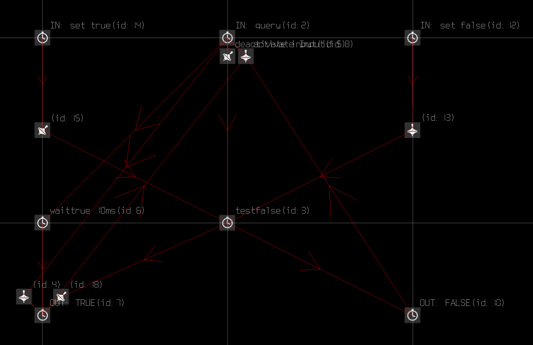
As you can see, the switch has three inputs and two outputs:
- IN: set true: Will set the switch to state true, but will produce no output signal
- IN: set false: Will set the switch to state false, but will produce no output signal
- IN: query: Triggering this will query the state of the switch and will either lead to a false or a true output signal
- OUT: true: Indicates that the switch state is true
- OUT: false: Indicates that the switch state is false
The switch is based on the fact that in the BoX ME a Timer Trigger can have two states: it can either be activated or deactivated. When the switch is queried and the
testfalse timer is active, it will deactivate the
true output and trigger a
false output. If it got deactivated, the
waittrue timer will produce a
true output after 10 ms. Cool, huh?

Please note that the switch will lead to a
false output by default.
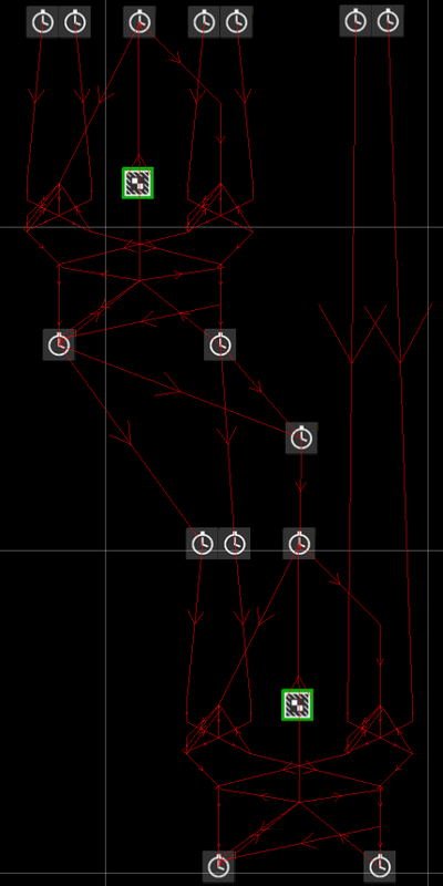
2. Ten way switch:Sometimes just two states might not be sufficient to trace what's going on in a mission. That's where the next group, the
ten way switch might come in handy (sorry, but I had to leave out the MCU names because it would get messy otherwise):
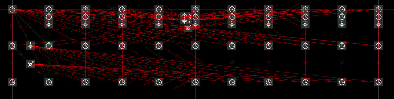
The switch has eleven inputs and eleven outputs. The topmost row of timer MCUs are the inputs, the lowest row are the outputs.
The leftmost timer queries the switch state and will lead to one of the outputs to fire, depending on the switch state. The other inputs will set the switch state to state 1 ... 10, beginning from the second timer MCU. Please note that those will
only set the switch state and will
not trigger an output singal.
The lowest MCU row are the outputs. If the switch got queried, they will show the switch state from 0 (leftmost) to 10 (rightmost).
As you may have noticed it is impossible to set the switch state to 0. In fact this state shows that the switch has not yet been used. It will only be active if none of the states 1 to 10 has been set during the mission yet.
The idea behind the switch is again based on timer (de)activation: If a status is active, it's
check state timer (middle row) will be activated, all other
check state timers will be deactivated and therefore cannot produce an output signal.
3. Switch concatenation:If you should ever come around an occasion where even ten switch states are not enough, you can also concatenate two (or more ...) ten way switches. It works like this:
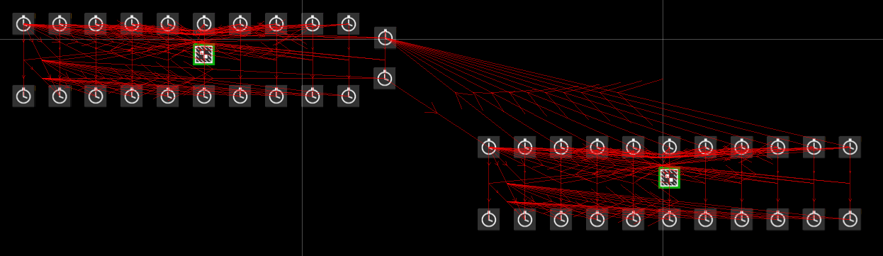
We sacrifice the state 10 of switch 1. It's output gets target linked to the
query input of switch 2. All
set state inputs of switch two get an additional target link pointing to the
set state 10 input of switch 1.
Now if you choose a state of switch two and query the overall state (with the
query input of switch 1!), switch 1 will lead to a state ten output. This one will query the state of switch 2 which will then lead to the desired state output.
Please note that in- and outputs of state 10 / switch 1 must not be used for any further signal processing!
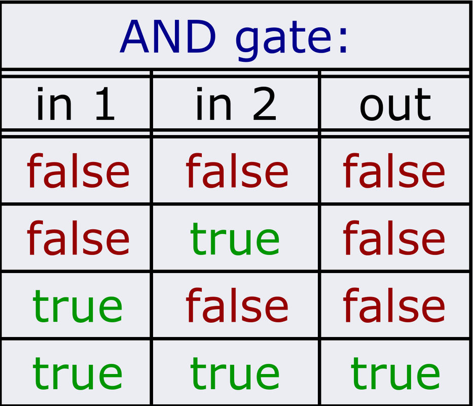
4. Logic gates:Now that we have the possibility to save a signal or a signal state, we will also like to process them further. If you make a dynamic mission you will soon come to the point where you will want to base your decisions on whether certain signals have been sent and others haven't, or whether some switch is in one position or not in another ..
That's where logic gates come into play. Depending on two input signals (each is either
false or
true) they produce one output signal which can be
false or
true.
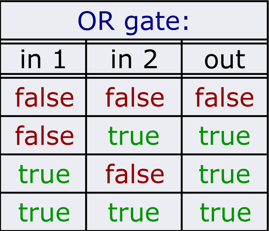
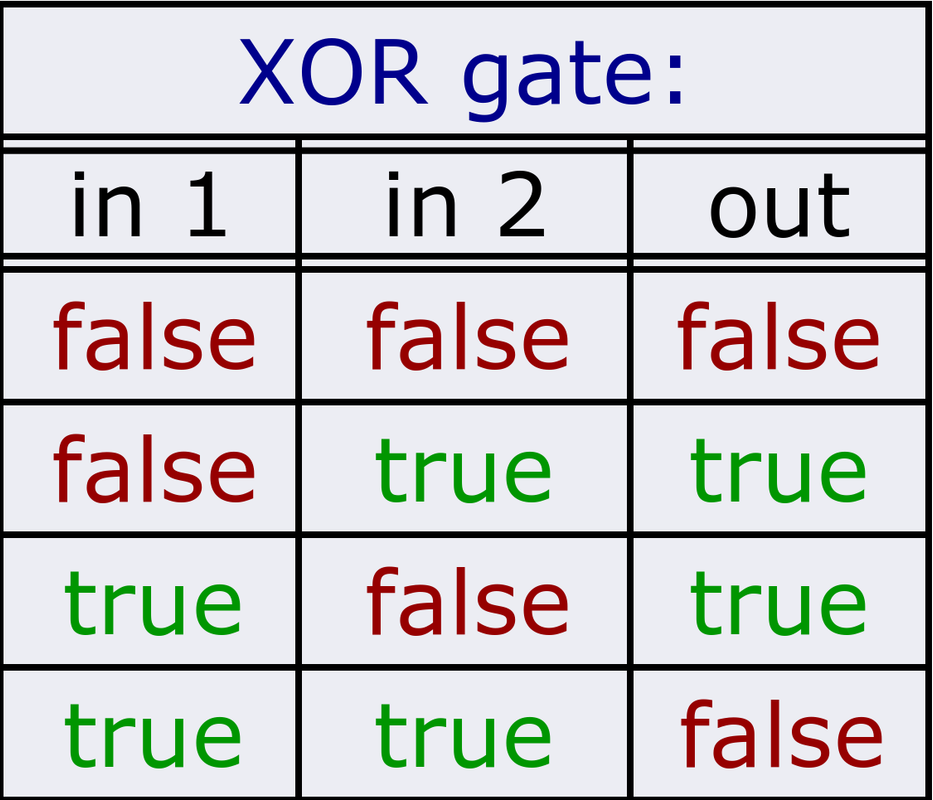
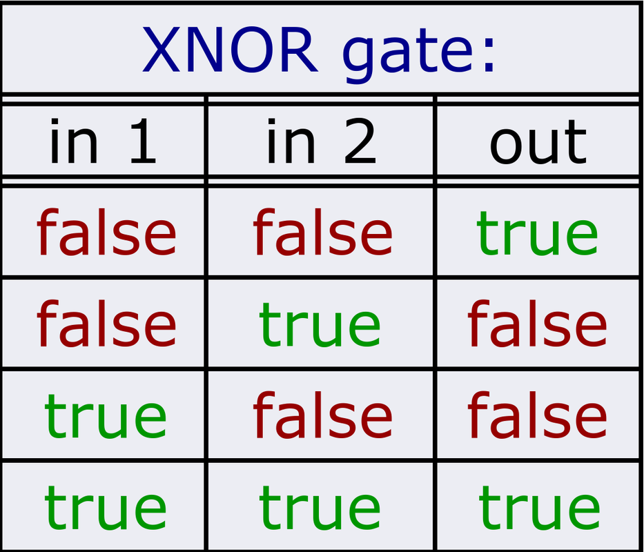
I have created six logic gate groups:
AND,
OR, NOT-AND (
NAND), NOT-OR (
NOR), exclusive OR (
XOR) and exclusive NOT-OR (
XNOR). You can find their truth tables below:


4.1. General structure:The signal processing in the logic gates is a little more complex and differs from gate to gate, therefore I will just discuss their structure in general here:
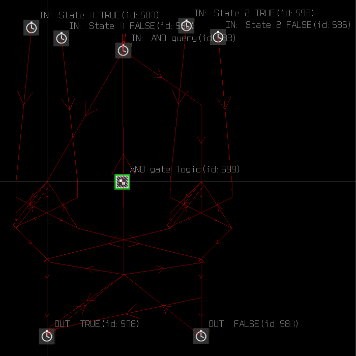
The basis of each logic gate are two boolean switches as introduced earlier.
Therefore each logic gate has five inputs and two outputs:
- IN: State 1 TRUE: Will set the state of input signal 1 to true, but will produce no output signal
- IN: State 1 FALSE: Will set the state of input signal 1 to false, but will produce no output signal
- IN: State 2 TRUE: Will set the state of input signal 2 to true, but will produce no output signal
- IN: State 2 FALSE: Will set the state of input signal 2 to false, but will produce no output signal
- IN: query: Triggering this will start the query process and will either lead to a false or a true output signal
- OUT: TRUE: Gets triggered if the result is true
- OUT: FALSE: Gets triggered if the result is false
4.2. Gate concatenation:Just like the switches the gates can also be concatenated - may it be to just allow more input signals for "one" gate or in order to combine different gates with each other. Below you can see how it is done:
The outputs of gate 1 are connected to the corresponding signal inputs of gate 2. Furthermore they are connected to a 5 ms timer which will start the query process in gate 2. In this example we therefore get an AND gate that allows three input signals.
5. Multiplexer:The multiplexer is to be used when more consumers depend on one state switch, but should not receive it at the same time. Example: AI flight on spawn depending its skill on the number of players spawned. Ten minutes later the next flight spawns, it would be bad if the logic of the first flight got called again!
In my implementation the MUX looks like this (shown here is the 5x5 MUX only, the others are too big to really see something):
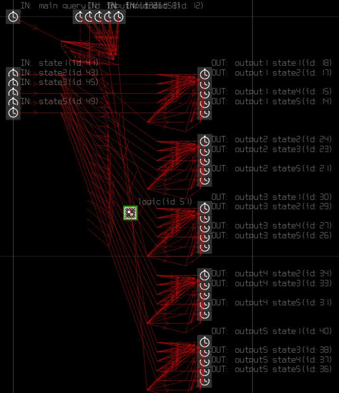
The 5x5 MUX has 11 inputs and 25 outputs:
- IN: state[1..5]: Will set the switch state (analog to ten way switch).
- IN: input[1..5]: Defines which output is to be used for the state signal.
- IN: main query: Will start the query process to return the state via the defined output.
- OUT: [...]: According to state and selected output.
The 10x10 MUX has 20 inputs and 110 outputs:
- IN state[1..10]: Will set the switch state (analog to ten way switch).
The query process is not started. - IN: input[1..10]: Defines which output is to be used for the state signal. After that the query process is started automatically, which will lead to the display of the state through the desired output.
- OUT: output[1..10] state[1..10]: indicating the state via the selected output.
- OUT: output[1..10] state undefined: indicates that the state has not been set yet via the selected output
The 10x10 MUX has 21 inputs and 110 outputs:
- IN state[1..10]: Will set the switch state (analog to ten way switch)
The query process is not started. - IN: input[1..10]: Selects the output gate which shall receive the signal through the next query.
The query process is not started. - IN: query: starts the query process.
- OUT: output[1..10] state[1..10]: indicating the state via the selected output(s), or none if none is selected.
- OUT: output[1..10] state undefined: indicates that the state has not been set yet via the selected output. Is not triggered if no output gate was selected.
Please note:- In the 5x5 MUX, both a state and an input needs to be triggered before main query, otherwise you will get not output signal!
On the 10x10 multi MUX one input gate needs to be triggered to produce an output signal.
The normal 10x10 MUX has no such limitations. - When query is triggered, the MUX will not be able to receive a change of state or input for ~300ms. Any signal incoming during this period will get lost.
- Only one output gateway can be active per query. This does NOT apply for the 10x10 multi MUX.
Credits- Idea and implementation: SAS~Skylla
- Many thanks to SAS~Storebror for beta testing!
Readme+---------------------------------------------------------------------------------------------
| Logic gates and switches for BoX ME, v1.2
+---------------------------------------------------------------------------------------------
Contents:
- boolean switch group
- boolean switch small group
- ten way switch group
- ten way switch small group
- AND gate group
- OR gate group
- NAND gate group
- NOR gate group
- XOR gate group
- XNOR gate group
- 5x5 Multiplexer group
- 10x10 Multiplexer group
- 10x10 Multiplexer (multi gate) group
+---------------------------------------------------------------------------------------------
| Installation:
+---------------------------------------------------------------------------------------------
Import the groups via ME.
+---------------------------------------------------------------------------------------------
| How To Use It:
+---------------------------------------------------------------------------------------------
1. Boolean switch:
The switch has three inputs and two outputs:
- IN: set true: Will set the switch to state true, but will produce no output signal.
- IN: set false: Will set the switch to state false, but will produce no output signal.
- IN: query: Triggering this will query the state of the switch and will either lead to
a false or a true output signal.
- OUT: true: Indicates that the switch state is true.
- OUT: false: Indicates that the switch state is false.
The Boolean switch small group was made extra small in its dimensions on the map so it
does not intefere too much with other MCUs placed around
2. Ten way switch:
The switch has eleven inputs and eleven outputs:
- IN: query: Triggering this will query the state of the switch and will lead to an
output signal.
- IN: set state 1 .. 10: will set the switch state, but will produce no output signal.
- OUT: state 0: This output will only get triggered if no state has been set on the
switch yet.
- OUT: state 1 .. 10: Indicates the switch state.
You can concatenate two (or more) then way switches in order to get more possible states.
In order to do this, target link the state 10 output of switch 1 to the query input of
switch 2. All set state inputs of switch 2 get an additional target link pointing to the
set state 10 input of switch 1. Now if you choose a state of switch two and query the
overall state (with the query input of switch 1!), switch 1 will lead to a state ten
output. This one will query the state of switch 2 which will then lead to the desired
state output.
Please note that in- and outputs of state 10 / switch 1 must not be used for any further
signal processing!
The Ten way switch small group was made extra small in its dimensions on the map so it
does not intefere too much with other MCUs placed around
3. Logic gates:
In general each logic gate has five inputs and two outputs:
- IN: State 1 TRUE: Will set the state of input signal 1 to true, but will produce no
output signal.
- IN: State 1 FALSE: Will set the state of input signal 1 to false, but will produce no
output signal.
- IN: State 2 TRUE: Will set the state of input signal 2 to true, but will produce no
output signal.
- IN: State 2 FALSE: Will set the state of input signal 2 to false, but will produce no
output signal.
- IN: query: Triggering this will start the query process and will either lead to a false
or a true output signal.
- OUT: TRUE: Gets triggered if the result is true.
- OUT: FALSE: Gets triggered if the result is false.
You can find the truth tables for the switches below. "0" stands for false, "1" for true.
AND OR NAND NOR XOR XNOR
A | B | AB A | B | AB A | B | AB A | B | AB A | B | AB A | B | AB
0 | 0 | 0 0 | 0 | 0 0 | 0 | 1 0 | 0 | 1 0 | 0 | 0 0 | 0 | 1
0 | 1 | 0 0 | 1 | 1 0 | 1 | 1 0 | 1 | 0 0 | 1 | 1 0 | 1 | 0
1 | 0 | 0 1 | 0 | 1 1 | 0 | 1 1 | 0 | 0 1 | 0 | 1 1 | 0 | 0
1 | 1 | 1 1 | 1 | 1 1 | 1 | 0 1 | 1 | 0 1 | 1 | 0 1 | 1 | 1
You can also concatenate logic gates. For this, the outputs of gate 1 are connected to
the corresponding signal inputs of gate 2 (true to true, false to false).
Furthermore they are connected to a 5 ms timer which will start the query process in
gate 2.
4. Multiplexer:
A multiplexer can be used when more consumers depend on one state switch, but should not
receive the result at the same time. Example: AI flight on spawn depending its skill on the
number of players spawned. Ten minutes later the next flight spawns, it would be bad if the
logic of the first flight got called again!
The 5x5 MUX has 11 inputs and 25 outputs:
- IN: state[1..5]: Will set the switch state (analog to ten way switch)
The query process is NOT started.
- IN: input[1..5]: Defines which output is to be used for the state signal.
The query process is NOT started.
- IN: main query: Will start the query process to return the state via the defined output
- OUT: output[1..5] state[1..5]: indicating the state via the selected output.
The 10x10 MUX has 20 inputs and 110 outputs:
- IN state[1..10]: Will set the switch state (analog to ten way switch)
The query process is NOT started.
- IN: input[1..10]: Defines which output is to be used for the state signal. After that
the query process is started automatically, which will lead to the display of the state
through the desired output.
- OUT: output[1..10] state[1..10]: indicating the state via the selected output.
- OUT: output[1..10] state undefined: indicates that the state has not been set yet via
the selected output
The 10x10 MUX has 21 inputs and 110 outputs:
- IN state[1..10]: Will set the switch state (analog to ten way switch)
The query process is NOT started.
- IN: input[1..10]: Selects the output gate which shall receive the signal through the
next query. The query process is NOT started.
- IN: query: starts the query process.
- OUT: output[1..10] state[1..10]: indicating the state via the selected output(s), or
none if none is selected
- OUT: output[1..10] state undefined: indicates that the state has not been set yet via
the selected output. Is not triggered if no output gate was selected.
PLEASE NOTE:
- On the 5x5 MUX, both a state and an input needs to be triggered before main query,
otherwise you will get NO OUTPUT SIGNAL!
On the 10x10 multi MUX at leads one input gate needs to be triggered to produce an
output signal.
The normal 10x10 MUX has no such limitations
- When query is triggered, the MUX will not be able to receive a change of state or input
for ~300ms. Any signal incoming during this period will get lost.
- Only one output gateway can be active per query. This does NOT apply for the
10x10 multi MUX.
+---------------------------------------------------------------------------------------------
| Versions:
+---------------------------------------------------------------------------------------------
- v1.0: initial public release
- v1.1: New switches added:
+ boolean switch (small version)
+ ten way switch (small version)
+ 5x5 MUX
- v1.2; New switches added:
+ 10x10 MUX
+ 10x10 MUX (multi gate version)
+---------------------------------------------------------------------------------------------
| Credits:
+---------------------------------------------------------------------------------------------
- Idea and implementation: SAS~Skylla
- Many thanks to SAS~Storebror for beta testing!
+---------------------------------------------------------------------------------------------
| Bug reports:
+---------------------------------------------------------------------------------------------
The only spot I will look out for bug reports are this Mod's release topics
on www.sas1946.com
I will NOT care for bug reports that do not contain both of the following:
- a DETAILED description of the problem and how it can be reproduced (minimal working example)
- the acknowledgment that you have read this readme. This means you should literally write
"I have read and understood the readme" somewhere in your post.
I repeat, bug reports missing any of these points will get ignored ...
To those who may think of writing a help request via PM to me: Don't you dare!
Use the forum so others can benefit from the answer as well ;)
>>>>> I hope you'll have a blast with this! See you in the skies! <<<<<
______________________________________________________________________________________________
02.05.2020, SAS~Skylla @ www.sas1946.com
Best Regards,
skylla


 Author
Topic: logic gates and switches (Read 4199 times)
Author
Topic: logic gates and switches (Read 4199 times)